From a Burned Hybrid Transmission Motor to a Custom NTC Signal Converter: A Kia Optima Hybrid Case Study
Based on the Hyundai service bulletin and similar repair cases, this issue may also be relevant to Hyundai Sonata Hybrid YF models from the same production years.

1. Introduction
This story started with a decision that many car enthusiasts can probably understand. Before the Kia Optima Hybrid, I had a third-generation Hyundai Accent. It was a simple, reliable, and understandable car that did not create any serious problems. It simply did its job: it drove, did not demand too much attention, and was relatively cheap to maintain.
But at some point, I wanted something more modern.
I wanted a car that would be more than just basic transportation. I wanted something more interesting and more technologically advanced: more comfort, a better appearance, an automatic transmission, a hybrid system, better fuel economy in the city, and at the same time good performance. The Kia Optima Hybrid looked like exactly that kind of car — a large comfortable sedan that combined a gasoline engine with an electric motor.
Another thing that attracted me was that this was not a slow “economy car.” The combined output of the hybrid powertrain is over 200 horsepower, so the car promised not only better efficiency than a regular large sedan, but also enough power for daily driving. That combination was exactly what I liked: modern technology, comfort, fuel economy, and the feeling that there was still enough power under the hood.
I bought the car for about $10,500 with a trade-in and additional payment: I gave away my third-generation Hyundai Accent and paid the difference. From a purely practical point of view, the Accent was the simpler and safer choice in terms of future repairs. But I did not want only a trouble-free car. I wanted something more interesting, more technological, and from a higher class.
At the time of purchase, the Kia Optima Hybrid felt like exactly that kind of upgrade. It looked more solid, drove more pleasantly, had better comfort, and gave the feeling of a more modern car. Back then, I did not yet know that together with comfort and hybrid technology, I would also get a deep dive into diagnostics, repairs, and the specific problems of a complex hybrid transmission.

I got spotted by spotters
Back to top ↑2. Vehicle Background
The 2015 Kia Optima Hybrid is not just a regular Optima with a different badge. It is significantly different from the gasoline, LPG, and diesel versions because the control logic of the vehicle is completely different.
In a conventional car, when the driver presses the accelerator pedal, they are essentially controlling how much fuel or air-fuel mixture should be delivered to the engine in order to get the desired response. In a hybrid, it feels different. The driver is not directly requesting a specific engine behavior. Instead, the driver is essentially requesting a certain amount of torque or acceleration at the wheels. The car then decides by itself how to provide it: using the gasoline engine, the electric motor, the high-voltage battery, or all of them together.
This is the main difference of this type of vehicle. The hybrid system constantly makes decisions on its own: when to start the internal combustion engine, when to shut it off, when to drive on electric power, when to assist the gasoline engine with the electric motor, when to charge the battery, and when to use regenerative braking during deceleration. For the driver, it looks simple — you press the pedal, and the car moves. But internally, at that moment, a complex energy management logic is working.
In my case, the car was a 2015 Kia Optima Hybrid, TF generation, facelift version. It is not a plug-in hybrid, so it does not need to be charged from an external power outlet. The battery is charged while driving, during regenerative braking, and by the gasoline engine. In everyday use, it feels like a normal car, but with a much more complex and interesting operating logic.
This technology was one of the reasons why the car attracted me. Compared with my previous Hyundai Accent, the Optima Hybrid felt like a completely different level of vehicle. It was larger, more comfortable, quieter, more pleasant to drive, and much more interesting from a technical point of view.
At the time of purchase, the car did not look perfect, but its problems seemed relatively minor. It was noticeable that the mileage had most likely been slightly rolled back. Also, the washer fluid level sensor was not working, so the car did not correctly show the condition of the washer fluid reservoir.
Another issue was related to the multimedia system. Since the car came from the American market, the radio worked only on odd FM frequencies. In Ukraine, this is inconvenient because some local radio stations simply cannot be tuned. In addition, the car did not have a modern Android head unit. It had a standard factory multimedia system — basically a regular factory radio unit with a screen and basic functions.
So, from the beginning, the car already had several small issues, but they did not seem critical. The mileage, the washer fluid level sensor, and the limited radio frequency range looked more like everyday inconveniences than serious technical problems. Compared to the overall feeling of the car, they did not outweigh its main advantages: comfort, appearance, the hybrid system, fuel efficiency, and the feeling of a more modern car compared with the Accent.
At the time of purchase, I understood that a hybrid would be more complicated than a conventional car. But back then, I saw it more as an interesting feature than as a potential problem. It felt like I was getting a modern, comfortable, and fuel-efficient car with intelligent powertrain logic. Only later did it become clear that this level of technology requires a completely different approach to diagnostics and repair.
Back to top ↑3. Early Warning: Clutch Pump Fault and P1744
About a week after buying the car, I got the first serious reason to worry. When the car was cold, a transmission-related fault started appearing from time to time. As far as I remember, it was P1744. The strange thing was that the fault was not permanent: it could appear on a cold start and then disappear by itself later.
At first, this was confusing. On one hand, the car was driving normally. There was no feeling that the transmission was falling apart, no obvious harsh shifts, no slipping, and no complete loss of drive. On the other hand, the fact that a transmission-related fault appeared almost immediately after buying a hybrid car was already unpleasant. Especially because I had just moved from a simple Hyundai Accent, which did not create this kind of problem.
I started searching online and gradually found information suggesting that this fault could be related not just to the transmission in general, but specifically to the clutch system — more precisely, to the clutch pump. From what I found, the problem could be caused by worn Teflon rings inside the unit. Due to oil starvation or insufficient lubrication, these rings can wear out, and after that the system can no longer maintain the required oil pressure for proper clutch operation.
So the issue did not look like a small sensor problem that could be fixed quickly. It looked like a potentially serious problem inside the hybrid transmission. That was what started to bother me. I had bought a car that was not cheap, expecting to get a more modern, comfortable, and technologically advanced vehicle, and after only one week I was already dealing with a fault that pointed toward transmission repair.
After that, I contacted a mechanic to understand how bad the situation was and whether it could be repaired partially. His answer was roughly like this: “Look, brother, the cost of this kind of repair is close to a full transmission rebuild. In any case, the transmission has to be removed and opened. And if you are already removing and opening it, there is no real point in repairing only one small part — you should inspect, service, and repair everything inside that needs attention.”
In other words, a partial repair did not make much sense in this situation. To reach the problematic unit, a large amount of work would be required anyway. And if that amount of work is already being done, it is logical not to limit the repair to only the pump or one element, but to check the overall condition of the transmission.
Since the fault did not noticeably affect drivability at that time, the mechanic advised me not to open the transmission immediately, but to keep driving and observing the car. His logic was simple: while the car still drives normally, there is no point in urgently spending a large amount of money on a repair that is close in cost to a serious transmission rebuild. It would be better to drive it, see whether the problem gets worse, and during that time possibly prepare money for a proper repair if it really becomes necessary.
From a technical point of view, that advice made sense. But psychologically, the situation was unpleasant. I had just bought a car that seemed good, not cheap, and much better than my previous car. I wanted to enjoy the purchase, not immediately think about a possible rebuild of a hybrid transmission.
The main stress was not even that the car was driving badly at that moment. It was actually driving normally. The stress came from the fact itself: I had invested in a car that was supposed to be an upgrade, and almost immediately I received a complex and potentially expensive problem. At the same time, I understood that many people drive cars with much bigger issues and do not worry about them at all. But in my case, this fault seriously damaged the feeling of the purchase, because it touched exactly the component that people usually fear most in a hybrid car — the complex transmission.
At that moment, I decided to follow the mechanic’s advice: not to open the transmission immediately, but to keep driving, observe the car’s behavior, and wait to see whether the problem would become more serious. At the time, it felt like a compromise between common sense and financial reality. Only later did this early fault begin to look not like a separate minor issue, but possibly as the first symptom of a deeper problem.
Back to top ↑4. Possible Cooling Failure and Motor Overheating Hypothesis
After the first appearance of the clutch pump-related fault, I continued driving the car for about seven months. During that period, the error did not completely disable the vehicle. The car still drove normally most of the time, and there were no obvious symptoms that clearly said: “Stop driving immediately.” Because of that, it was easy to treat the situation as an unpleasant but not urgent transmission fault.
However, psychologically, it was always in the background. I was constantly in a small state of stress because I knew that something inside the hybrid transmission was not completely right. The car was usable, but the fault was already there. Every time it appeared, especially on a cold start, it reminded me that the problem had not gone away.
At that time, I mostly thought about it as a clutch pump issue. In my mind, it was mainly a problem of clutch pressure, pump operation, or some internal hydraulic control. I did not fully understand the possible connection between that pump and the cooling of the area where the hybrid electric motor is located.
Only later did I start looking at the situation differently. If the clutch pump does not circulate oil properly around the clutch area, then the problem may not be limited only to clutch operation. The same oil can also work as a cooling medium for that section of the transmission. And in that same area, there is the traction electric motor of the hybrid system.
This changed the meaning of the entire fault for me. What I had considered for seven months to be just an annoying intermittent error may actually have been seven months of insufficient oil circulation and constant additional heat stress for the electric motor.
In other words, the pump fault may have created a situation where the motor was still working, the car was still driving, but the cooling conditions were no longer normal. The electric motor could have been operating in a hotter environment than it should have. Not necessarily overheating instantly, not necessarily failing immediately, but slowly accumulating thermal damage over time.
This is my main hypothesis: the clutch pump problem may have reduced oil circulation in the clutch and motor area, and because that oil also helps remove heat, the traction motor may have been exposed to repeated or continuous overheating. Over several months, that could have degraded the insulation of the motor windings.
At the time, I did not see it that way. I thought I was driving with a stupid intermittent error that was annoying but not critical. Later, after the electric motor failed, the same seven months started to look completely different. They may not have been just seven months of driving with a fault code. They may have been seven months during which the electric motor was slowly overheating and losing its insulation strength.
I cannot prove this with absolute certainty, because I did not have temperature logs from inside the motor during that period. But the sequence of events makes this hypothesis very plausible: first, a clutch pump fault; then months of driving with that fault; then a major electric motor failure. From a system point of view, it is reasonable to suspect that poor oil circulation and insufficient cooling could have played a major role in what happened next.
Back to top ↑5. Burned Internal Electric Motor and Three Failed Windings
The main failure happened in the middle of August. I was driving home from work, the car was already fully warmed up, and by the time the failure happened I had driven about 8 kilometers. So this was not a cold-start situation or the first few minutes of driving. The car was already operating in its normal thermal condition.
I needed to make a U-turn through a gap between two one-way sections of the street. I started to pull out, pressed the accelerator, and at that moment there was wheel slip. Almost immediately after that, the car started beeping with warnings. It stopped driving normally and began to shut down.
It was a very unpleasant moment because the failure did not happen in a parking lot or in calm conditions. It happened during a road maneuver. I barely managed to park the car, and then some people helped me move it away from the exit area where it had stopped in an emergency. The car had to be moved so that it would not block traffic or create a dangerous situation.
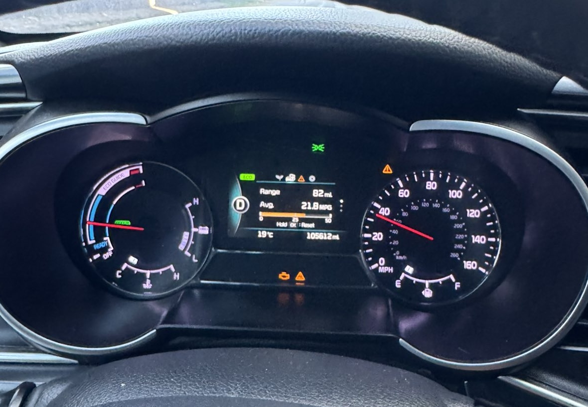
The first thing I understood after the stop was that the gasoline engine could start and run, but the car would not drive. A HEV warning appeared on the dashboard, meaning a hybrid system fault. That immediately showed that the problem did not look like a normal engine failure or a small electrical issue.
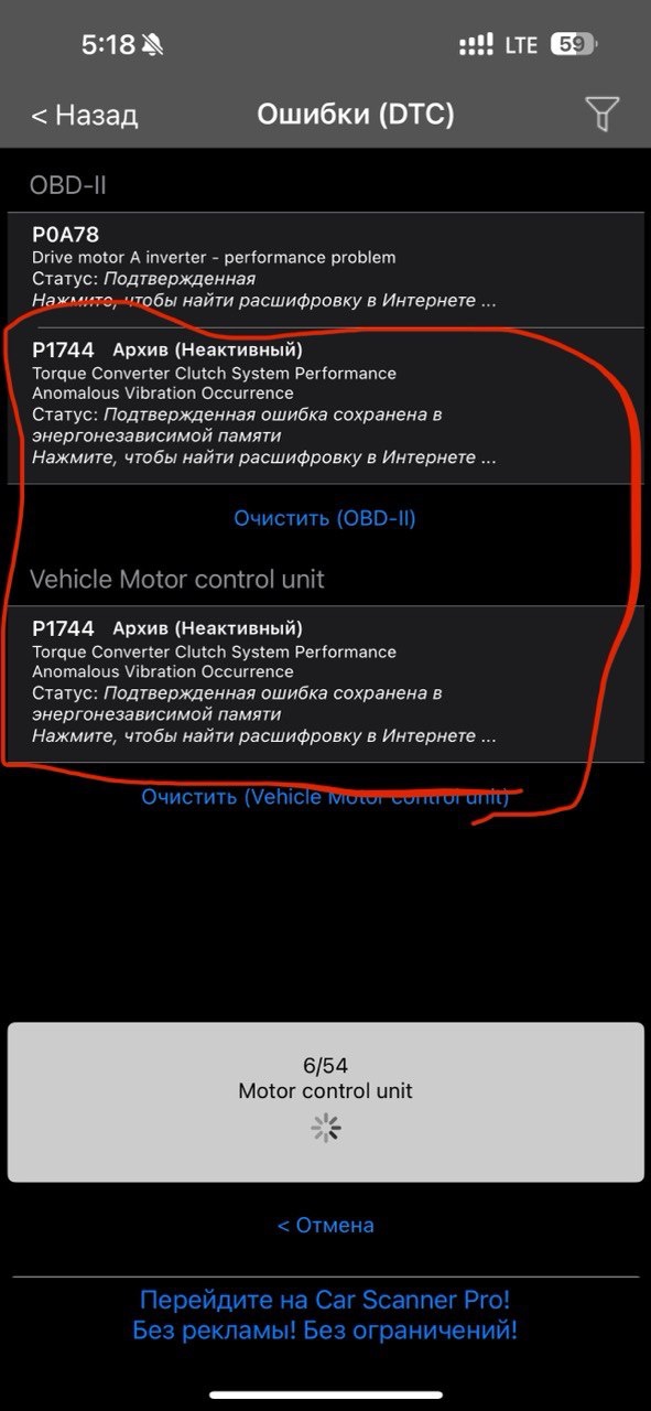
After that, I scanned the car and saw several fault codes. The screenshot showed a few important ones: P0A78 — Drive Motor “A” Inverter Performance Problem. This fault was active and confirmed. It pointed to a problem in the traction motor or inverter system. In the context of this failure, this was the most serious code because it directly related to the hybrid drive system.
There was also P1744 — Torque Converter Clutch System Performance / Anomalous Vibration Occurrence. This fault was stored in history and marked as inactive. It appeared both in the general OBD-II section and in the Vehicle Motor Control Unit. This was the same fault that had appeared earlier on cold starts and was related to the clutch system or clutch pump.
For me, this was important because the screenshot showed two parts of the story at the same time. On one hand, the old P1744 fault remained in memory as an earlier symptom. On the other hand, at the moment of the real failure, a much more serious active fault appeared — P0A78, related to the traction motor or inverter.
I also started checking the car myself. One of the first things I did was measure the 12-volt battery in the trunk with a multimeter. I saw that it was discharging quickly. That made the situation even more stressful, because if the 12-volt battery died completely, I could lose normal access to some of the car’s systems.
To avoid being locked out of the car or losing access, I took several practical steps right away. I slightly lowered one of the windows, checked that I had the mechanical key, and started figuring out how to open the trunk if the electrical power was lost. That was when I first learned that the trunk in this car can be opened with a small cable loop accessible from the rear seat area.
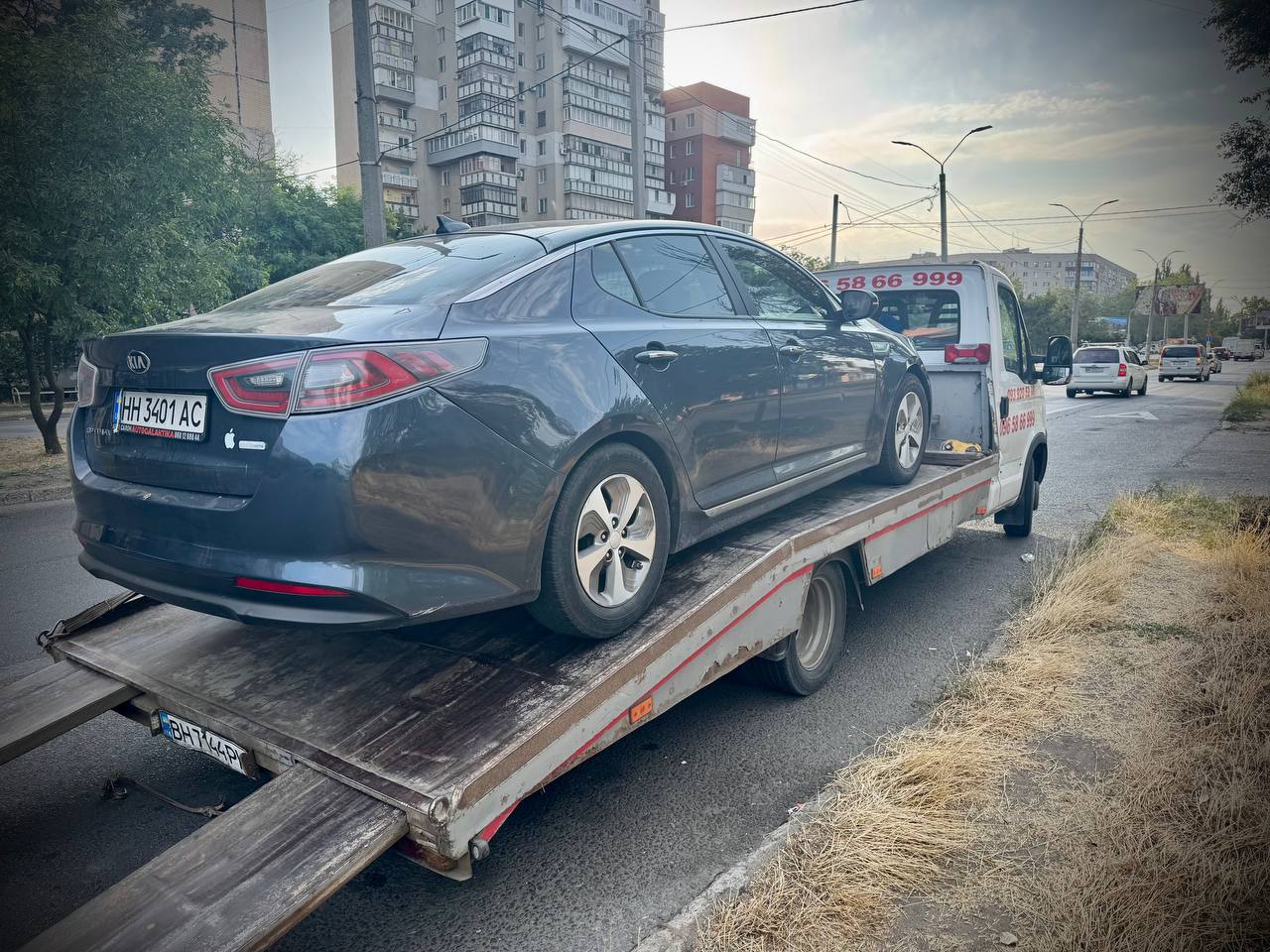
After that, all I could do was wait for a tow truck to take the car to the repair shop. At that moment, the situation no longer looked like a random fault or a temporary glitch. It looked like a serious failure of the hybrid drive system. The gasoline engine could run, but the car could not move normally, and the active P0A78 fault pointed directly toward the traction motor or inverter area.
Later, after further diagnostics, it became clear that the problem was not just electronics or a random fault code. The internal traction electric motor inside the transmission was damaged, and all three of its windings were burned. This became a logical continuation of the previous hypothesis: if the clutch pump had been working incorrectly for several months and had reduced oil circulation in the clutch and motor area, that area could have been overheating. Eventually, this could have degraded the winding insulation and led to complete electric motor failure.
6. Replacement Transmission/Motor Assembly
After the car was taken to the repair shop, more specific diagnostics began. The previous symptoms and fault codes pointed toward a problem in the hybrid drive area, but it was necessary to understand what had physically failed. After testing, the worst suspicion was confirmed: all three phase windings of the traction electric motor were shorted to the housing.
In addition to that, the condition of the transmission oil was also bad. The oil was black, which further suggested overheating, contamination, or severe operating conditions inside the transmission. Together with the earlier P1744 fault related to the clutch system, this no longer looked like a random electronic glitch. It looked like a serious mechanical and electrical problem inside the hybrid transmission.
After that, we started checking possible repair options. In theory, my original transmission could be repaired. But the situation was complicated by the fact that the problem was not only the electric motor. I had already had the P1744 fault before, which was related to the clutch pump and most likely worn Teflon rings. So the electric motor repair would not be the only job. The clutch pump or clutch-related unit would also have to be addressed.
The electric motor itself could be sent for rewinding. According to preliminary estimates, that work would cost around $700–800. But there was a lot of uncertainty in that option. There was no guarantee that the motor would be rewound properly, that it would work reliably afterward, that it would not burn again, or even worse, that it would not damage other expensive components such as the inverter.
Separately, I also had to consider the cost of removing and installing the transmission. Removing the transmission and installing it back would cost $350. The transmission repair itself was estimated to start from about $1,200, and on top of that there would be the additional $700–800 for rewinding the electric motor. In the end, the total cost became quite high, with many unknowns.
Another problem was that all these jobs would have to be done in different places. One specialist would work on the transmission, another one would deal with the electric motor, someone else might do the rewinding, and then everything would have to be assembled, installed, and tested. I am not an automotive mechanic, and I do not have my own workshop where I can calmly experiment, remove parts, install them back, disassemble, modify, and test everything myself. Because of that, this repair path looked expensive, complicated, and risky.
After calculating everything, I came to the conclusion that a more logical option would be to find a known working used transmission from a dismantling yard. The idea was simple: buy a complete assembly, replace the oil, install it on the car, and avoid the risky combination of repairing my damaged transmission, rewinding the motor, and also dealing with the clutch pump issue.
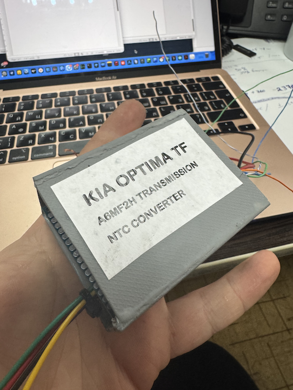
My mechanic helped me with this option. As a result, we found and bought a used hybrid transmission, model A6MF2H, which was used in the Kia Optima Hybrid TF generation from 2010 to 2015. The price of this transmission was about $2,000. After purchasing it, the transmission was installed on the car.
At that moment, this decision seemed to be the most rational one. Instead of investing in a complex repair with an uncertain result, I received a complete working assembly. Of course, it was still a risk because the transmission was used, but that risk seemed more controlled than repairing my damaged transmission with a rewound electric motor and additional clutch system repair.
Back to top ↑7. Discovery of the Temperature Sensor Mismatch
After installing the used transmission, I expected that the hardest part of the story was already behind me. The old transmission had a burned electric motor, and the replacement transmission was bought as a known working assembly. It was installed on the car, and logically, I expected that after reassembly the car would simply start and drive normally.
But after the car was assembled and started with the replacement transmission, new fault codes appeared. This was a very unpleasant shock both for me and for the mechanic. The situation immediately started to look bad: if the replacement transmission also had a problem, it could mean disputes with the supplier, a possible return of the part, another transmission removal, more lost time, more money, and the same difficult process of removal and installation again.
The screenshot taken after starting the car with the replacement transmission showed several fault codes. The most important one was P0A2D — Drive Motor “A” Temperature Sensor — Circuit High. This was a confirmed fault related to the traction motor temperature sensor. The phrase “circuit high” usually means that the control unit sees the signal level as too high, or the resistance in the sensor circuit as too high. This fault became the main clue that the issue might not be with the electric motor itself, but with the temperature sensor or its electrical characteristic.
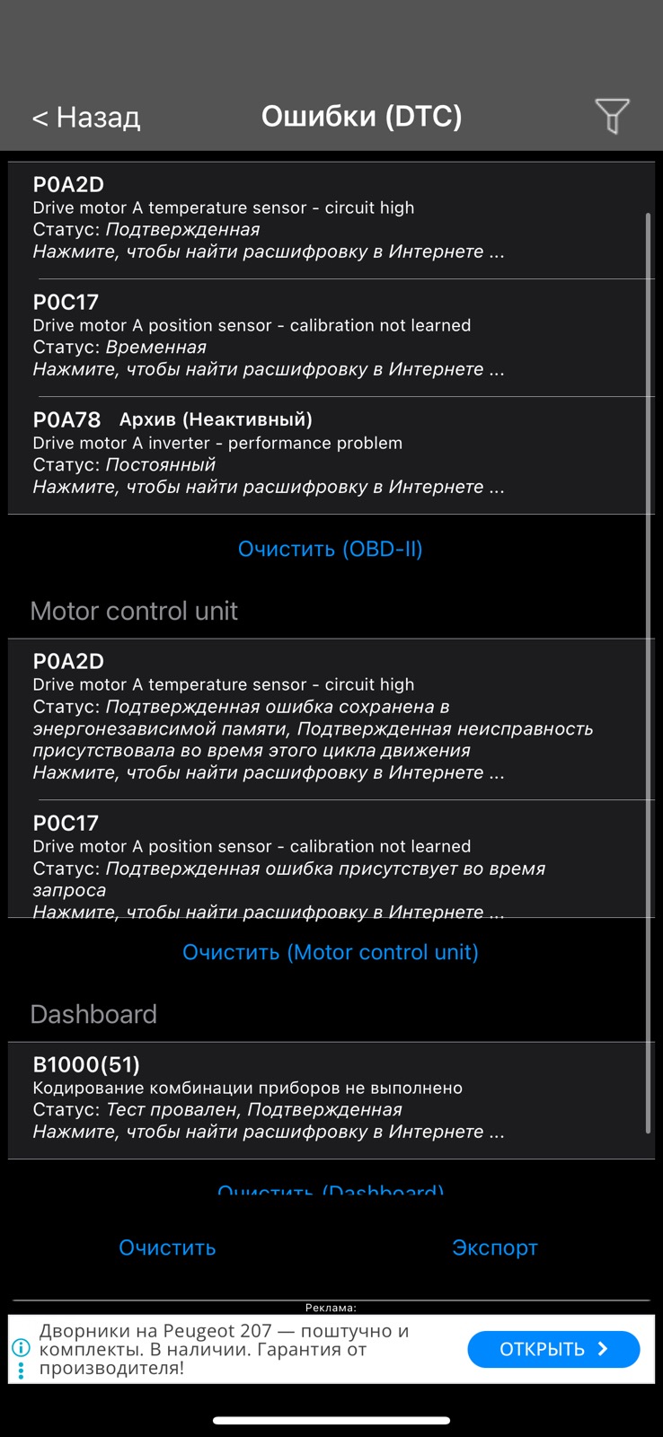
There was also P0C17 — Drive Motor “A” Position Sensor — Calibration Not Learned. This fault was related to the calibration of the electric motor position sensor. At the first stage, it looked less clear, but it could have been a consequence of replacing the transmission assembly or the need for adaptation after installing another unit.
P0A78 — Drive Motor “A” Inverter Performance Problem — remained in history as inactive. It was connected to the previous serious failure, when the old transmission had a problem with the traction motor or inverter system. B1000(51) in the dashboard module was related to instrument cluster coding and did not look like the main cause of the hybrid transmission issue.
At first, the most worrying thought was that the transmission we had bought might also be faulty. After all, we had bought it specifically to avoid a complicated repair of the original transmission, and now the car was again showing hybrid system-related errors. We tried clearing the fault codes, but they kept coming back. So this was not just an old stored message in memory that could be erased and forgotten. The system was really detecting a problem after startup.
The fault that attracted the most attention was P0A2D, related to the electric motor temperature sensor. It was different from the previous failure with the burned motor. Earlier, the main fault had been related to inverter or traction motor performance. Now, the control unit was directly complaining about the temperature sensor circuit. This changed the direction of diagnostics.
At this point, it became clear that the problem might not be that the replacement transmission was “dead.” Instead, the issue could be that its temperature sensor did not match what my car expected. In other words, the sensor could be physically installed correctly and could be functional by itself, but its electrical characteristic might not match the calibration of my vehicle’s control unit.
This was an important turning point in the whole story. At first, the faults after installing the replacement transmission looked like a disaster: as if the transmission would have to be removed again, the supplier would have to be contacted, and the whole process would start from the beginning. But gradually, another explanation appeared: maybe the transmission itself was mechanically and electrically usable, and the problem was specifically the mismatch of the traction motor temperature sensor.
From that moment, the repair was no longer just a transmission replacement. It became a separate electronic diagnostic task. I had to understand what exactly the control unit was seeing, what resistance or signal the sensor was producing, why the car considered it incorrect, and whether it was possible to adapt that signal so that the vehicle would see the correct temperature.
Back to top ↑8. Understanding the NTC Sensor Curve Problem
After the P0A2D fault appeared, we did not immediately understand that the issue could be related to a mismatch in the sensor characteristic. At first, the situation looked as if the electric motor temperature sensor itself was simply faulty or started working incorrectly after warming up.
The behavior of the car was quite specific. If we cleared the fault code, the car would start normally when cold. For the first few kilometers after clearing the code, everything looked almost normal: the car drove, the hybrid system worked, and there was no obvious emergency behavior right away. This created the impression that the problem was not permanent, but appeared only under certain conditions.
However, after the car had driven for some time and some distance, the same situation repeated. At some point, the transmission would give a noticeable kick, and then the electric motor temperature sensor fault would appear again. After that, the car could still continue driving, but it was already driving with an active fault. In other words, it did not completely stop, but the system clearly switched into an emergency or limited operating mode.
Then we would clear the fault again. The next morning, the car would again behave as if it was working properly: it would start, drive normally for a few kilometers, and then everything would repeat — a kick, the fault appearing again, and then continued driving with the active error. This scenario repeated more than once, so it became clear that the problem depended on operating conditions, most likely temperature.
At that stage, the first logical thought was that the temperature sensor itself might be damaged. For example, when cold, it could still produce a normal signal, but after heating up, it might stop working correctly. There could have been an internal break, a bad contact, or some internal defect that appeared only after reaching a certain temperature.
This seemed plausible because the fault was specifically described as Drive Motor “A” Temperature Sensor — Circuit High. That meant the control unit was seeing the signal level as too high or the resistance in the circuit as too high. In normal diagnostic logic, this could mean an open circuit, a bad contact, damaged wiring, or a sensor that goes out of range after warming up.
Because of that, at first we were not thinking about different calibrations or NTC curves. We were thinking about a normal sensor failure. It looked like that after reaching a certain temperature, the sensor stopped providing valid data, and the control unit immediately detected a fault. This also explained why, after cooling down and clearing the code, the car could again drive normally for some time.
But gradually the situation started to look more complicated. If the sensor had been completely dead, the fault would probably have appeared immediately after startup. In this case, it did not appear instantly. It appeared after some warming up or after a certain driving condition. This led to another idea: maybe the sensor was not “dead” in the direct sense. It could be working and changing resistance with temperature, but at some point its value went outside the range expected by the control unit of this particular car.
So the problem might not have been that the sensor did not work. The problem could be that its characteristic did not match the expected one. In the hybrid transmission, this temperature sensor is an NTC thermistor: its resistance changes depending on temperature. The control unit does not measure temperature directly. It sees an electrical signal and converts it into temperature using its internal calibration table.
If the installed sensor has a different NTC curve, then when cold, its value may still fall within the acceptable range. That is why the car may look normal at first. But after warming up, as the resistance starts changing, it may move in a direction or range that the control unit does not expect. At some point, the ECU sees a value that looks like an open circuit, excessive resistance, or circuit failure, and then the P0A2D fault appears.
This is how we gradually came to an important conclusion: the problem might not be a completely broken sensor, but a sensor from the replacement transmission with a different resistance-temperature relationship. In other words, the sensor was physically installed in the right place and reacted to temperature, but it was “speaking” to the control unit in a different electrical language.
This explained the strange behavior of the car: after clearing the fault, everything was normal when cold; then after a few kilometers, there was a kick, the fault appeared, and the car continued driving in fault mode. At some point, the control unit simply stopped accepting the sensor signal as valid. From that moment, it became clear that we needed to stop looking only for a “dead sensor” and start investigating its electrical characteristic and comparing it with what the car expected.
Back to top ↑9. Resistance Measurements and DZ Diagnostics
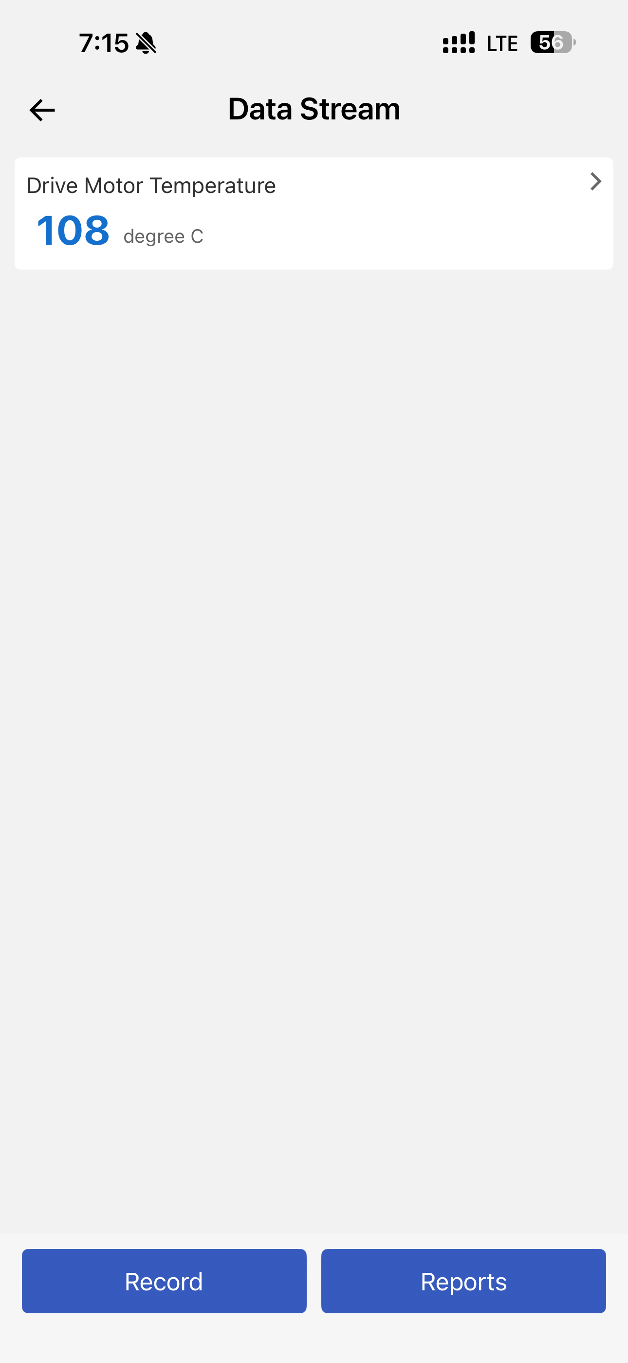
After we understood that the problem was repeating after some amount of warming up, the next step was to check the live data with a DZ diagnostic scanner. When I was driving together with the mechanic, he connected the scanner and watched the hybrid system parameters. The most important value for us was Drive Motor Temperature.
This was where we saw strange behavior. At first, the temperature value looked extremely low, almost like a negative value or something clearly unrealistic. Then, after some driving time, it could suddenly jump sharply upward. This did not look like normal gradual warming of the electric motor or the transmission. In a real thermal system, the temperature should not instantly jump by a large amount without a physical reason.
At first, we thought it looked like an open circuit or an unstable contact. The logic was simple: if the sensor or wiring was disconnecting somewhere, the control unit could see excessive resistance or an invalid signal. That matched the fault P0A2D — Drive Motor “A” Temperature Sensor — Circuit High. In other words, the system was seeing a signal that looked too high, or resistance in the sensor circuit that was too high.
But then I started searching deeper. Eventually, I found a Hyundai service bulletin for the Sonata Hybrid with a SAME hybrid system. This document directly describes EV motor temperature sensor faults and the codes P0A2B, P0A2C, P0A2D, and P0A2F. The important part was that the bulletin listed different resistance ranges for different model years.
According to that document, for 2010–2013 vehicles, the EV motor temperature sensor should measure approximately 112–143 kΩ at 20°C and 5.2–24.5 kΩ at 60–100°C. For 2014–2015 vehicles, the values are completely different: approximately 10.9–13.4 kΩ at 20°C and 0.9–3.3 kΩ at 60–100°C. So this was not a small difference. These were effectively two different types of NTC sensors with different temperature-resistance characteristics.
That became the key moment. Before that, we thought the sensor might simply be broken. But after reading the service bulletin, another explanation appeared: the sensor might be functional, but it could belong to a different transmission version. In other words, it could be physically installed in the transmission and react to temperature, but still produce resistance values that my car’s control unit did not expect.
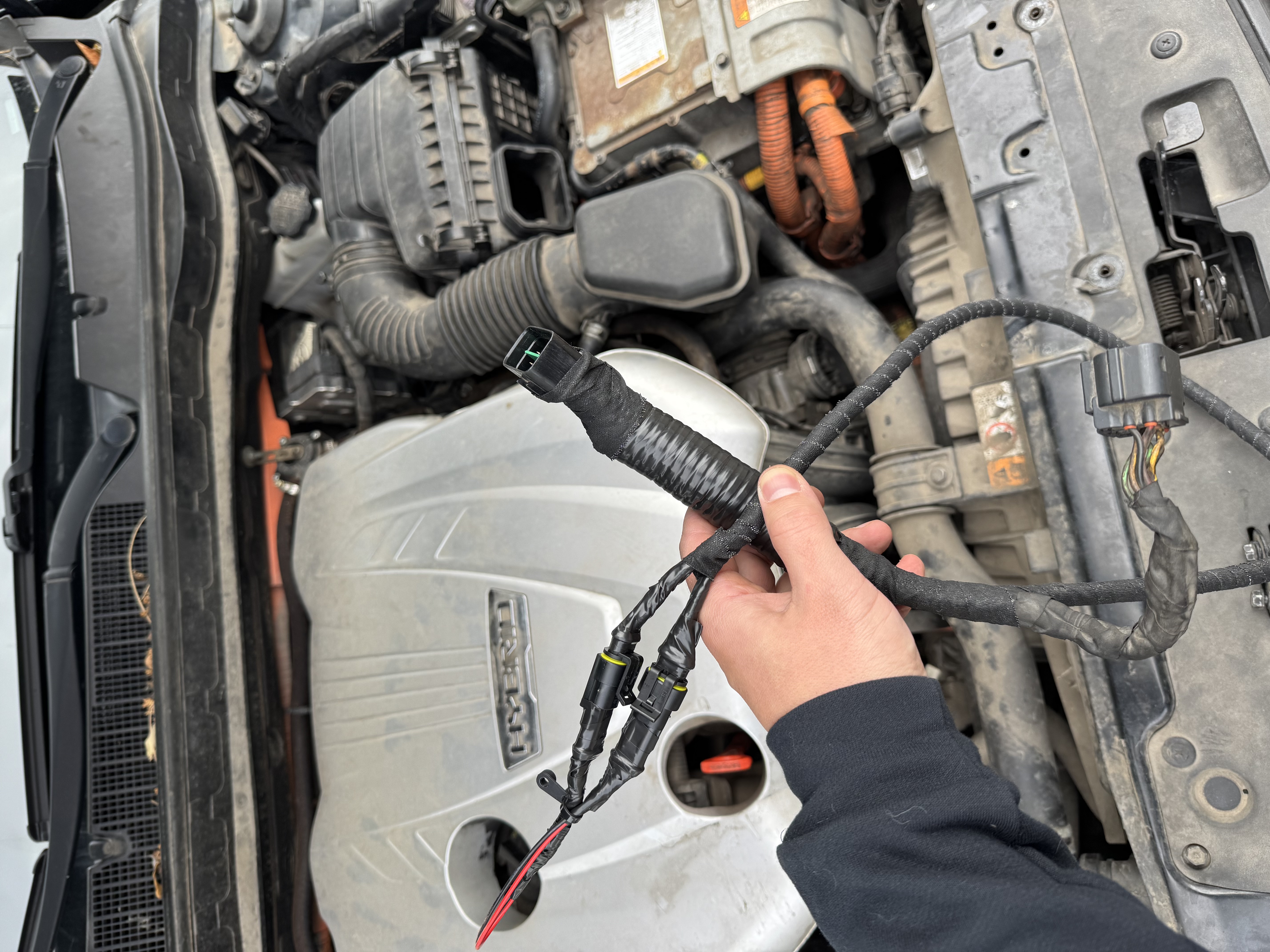
After that, I decided to check everything with a multimeter. I removed the air filter to get access to the required connector, disconnected it, and measured the relevant pins directly. This was no longer just an internet theory — it was a real measurement on my own car.
The measurement confirmed the suspicion. In my car, the control unit expected the newer type of sensor — roughly a 10 kΩ sensor at room temperature. But the transmission installed in the car had the older type of sensor — roughly around 100 kΩ. In other words, the transmission could be mechanically installed and could work, but the electric motor temperature sensor was electrically incompatible with my vehicle.
That explained the strange behavior. When cold, after clearing the fault, the system could still work for some time. But as the temperature changed, the sensor resistance moved outside the range expected by the control unit. As a result, the ECU interpreted the signal as a temperature sensor circuit fault, set P0A2D, the transmission gave a kick, and the car continued driving in fault mode.
Later, I also found a YouTube video from the United States about a very similar situation with a Hyundai Sonata Hybrid. In that case, a mechanic faced the same type of incompatibility: the factory or supplier shipped a transmission that looked correct by part classification, but the temperature sensor inside was from another version. The mechanic was collecting data and talking about legal action because, formally, the transmission seemed to match, but in practice, because of the different sensor, it could not work correctly with that specific car.
This finally confirmed that I was not dealing with a unique random problem, but with a real compatibility issue between different versions of the hybrid transmission. On paper, the transmission could look compatible, but the vehicle electronics expected another temperature sensor. And if the control unit sees the wrong NTC curve, it cannot correctly calculate the electric motor temperature.
After that, it became clear that simply clearing the faults or looking for a bad contact no longer made sense. The issue was not a random open circuit. It was the difference between two electrical sensor characteristics. The options were either to physically replace the sensor inside the transmission, which would again mean serious mechanical work, or to find a way to electronically adapt the signal from the old sensor to what my car’s control unit expected.
From that moment, I started thinking about the problem not as a “transmission repair” issue, but as a signal conversion task. I had a working sensor, but it was the wrong sensor for my ECU. I needed to make the control unit see not the actual resistance of that sensor, but the resistance that would correspond to the correct temperature curve for my version of the car. This led to the next stage — the first resistor experiments and the search for a way to make the system see a correct signal instead of simply hiding the fault.
Back to top ↑10. First Experiment: Parallel Resistor Correction
After it became clear that the problem was not a broken wire and not a completely dead sensor, the situation became technically and legally uncomfortable. Formally, every side had some truth. I wanted to receive a transmission that would work correctly with my car. The mechanic ordered and installed the transmission according to the part classification. The supplier, from their side, shipped a working transmission that physically fit the car and did not have a burned electric motor.
The problem was in a compatibility detail: the transmission was functional, but the electric motor temperature sensor inside it was not the type expected by my car’s control unit. Because of that, it was difficult to simply say that one specific person was clearly at fault. It did not look like a situation where the supplier had sent a completely defective part. But for me as the owner, the result was still unacceptable: the car was again driving with a fault.
Also, hybrid transmissions like the A6MF2H are not very common or easy to find. Returning this transmission, paying again for removal, searching for another one, waiting for delivery, negotiating with the supplier, and then paying for installation again would have meant even more money, time, and stress. We had already spent money on fluid, installation, and the whole replacement process. And at that point I had already been without the car for more than a month, which was very uncomfortable in everyday life.
So I decided to approach the problem as an engineering task. If the control unit sees the wrong sensor resistance, then in theory it should be possible to change that resistance so that it falls into the working range. At first glance, the task even seemed not too difficult: after all, it was “just a resistor.” At that moment, I still thought the solution might be simpler than it turned out to be.
The first idea was to solder an additional resistor in parallel with the temperature sensor. The goal was to reduce the total resistance of the old 100 kΩ-type sensor and bring it closer to the range expected by the control unit for the newer 10 kΩ-type sensor.
The principle of a parallel resistor is simple: the total resistance is always lower than the smallest of the two resistances. If a smaller resistor is connected in parallel with a high-resistance sensor, the control unit no longer sees the full resistance of the sensor. Instead, it sees a reduced equivalent resistance. The formula is: R_total = (R_sensor × R_parallel) / (R_sensor + R_parallel).
In practice, this moved the signal in the correct direction. But it quickly became clear that this method could not properly convert one temperature curve into another. The problem was not only that one sensor was roughly “100 kΩ” and the other was roughly “10 kΩ.” The problem was that these are NTC thermistors, and their resistance-to-temperature relationship is nonlinear. It does not simply change by a constant factor of ten across the whole temperature range.
Because of that, one parallel resistor could not turn the old curve into the correct new curve. It could only roughly compress the resistance range. In one part of the temperature range, the value could look more or less acceptable, but in another part it would be far from what the control unit expected.
As far as I remember, I selected a resistor somewhere around 3.3 kΩ. The exact value may have been slightly different, possibly in the 2.2–4.7 kΩ range, but based on the result, a value around 3.3 kΩ seems the most likely. A resistor like that, connected in parallel with the old 100 kΩ-type sensor, significantly reduced the total resistance and made the control unit see a temperature in a hot operating range.
As a result, I managed to make the control unit see not a temperature sensor fault, but a temperature value somewhere around 90–110°C. This was not an accurate measurement of the real electric motor temperature. It was a rough electrical correction that allowed the signal to fall into a range the ECU considered valid.
At that moment, this seemed acceptable as a temporary solution. The car could drive without constantly triggering the P0A2D fault, and I gained some time to look for a better solution. I understood that it was not ideal: the control unit was basically seeing not the real temperature, but a kind of “stable hot” temperature. But compared with constant transmission kicks, fault mode, and the possibility of removing the transmission again, it looked like a workable compromise.
This experiment was important not as a final solution, but as a proof of concept. It showed that the problem was truly electrical and related to the resistance value seen by the control unit. If the resistance was shifted in the right direction, the fault disappeared or at least did not appear immediately. That meant it should be possible to create a device that would not just roughly fix the temperature in one range, but actually convert the signal from the old sensor into the correct curve expected by the newer control unit.
After that, it became clear that one resistor was only a temporary workaround. It helped me buy time and confirmed the direction, but it did not solve the problem properly. A smarter converter was needed — one that could read the real resistance of the sensor, calculate the temperature, and then provide the control unit with a signal corresponding to the expected 10 kΩ NTC curve.
Back to top ↑11. First Converter Prototype
After the experiment with a single parallel resistor, it became clear that the problem could really be solved electrically. If the control unit saw a correct or at least acceptable resistance value, the temperature sensor fault did not appear immediately. But one resistor could not be a proper solution because it did not convert one NTC curve into another. It only roughly forced the signal into a certain range.
So I started thinking about how to build a real resistance converter. The idea was to read the actual resistance of the old electric motor temperature sensor, calculate the approximate temperature, and then provide the control unit with a resistance value that would correspond to the newer 10 kΩ sensor expected by my car.
At first, I looked into digitally controlled potentiometers. On paper, this seems like a logical solution: the microcontroller measures the temperature, and the digital potentiometer sets the required resistance. But in practice, this option quickly turned out to be unsuitable. Some digital potentiometers did not have the required resistance range. Others had too much wiper resistance, not enough resolution, or were simply not well suited for this automotive task, where the control unit expects the behavior of a normal passive sensor.
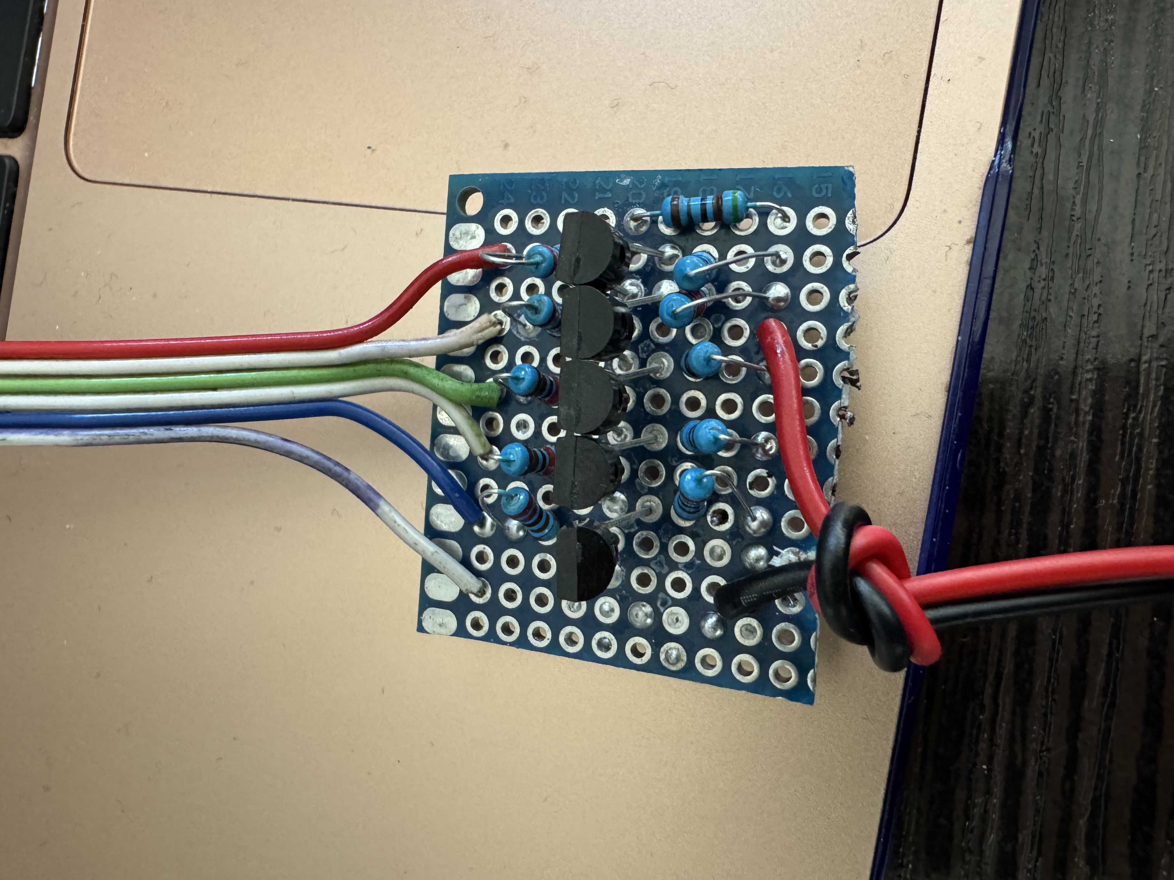
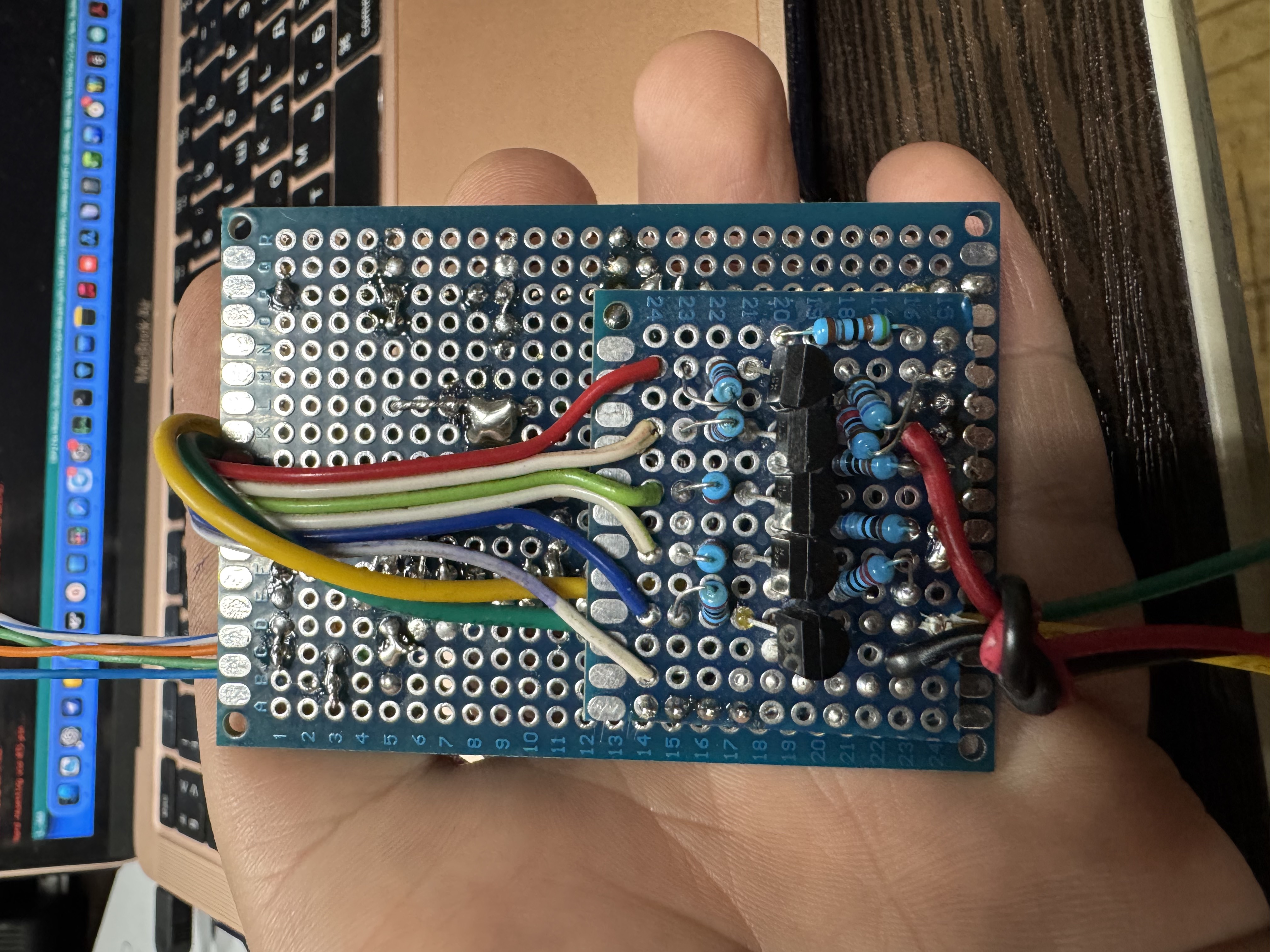
After that, I came to a rougher but more reliable solution: a resistor bank. Instead of trying to generate any smooth resistance value, the circuit would have one base resistor and several additional resistor branches that could be connected in parallel. Depending on the calculated temperature, the microcontroller would turn different branches on or off, and the equivalent output resistance would change in steps.
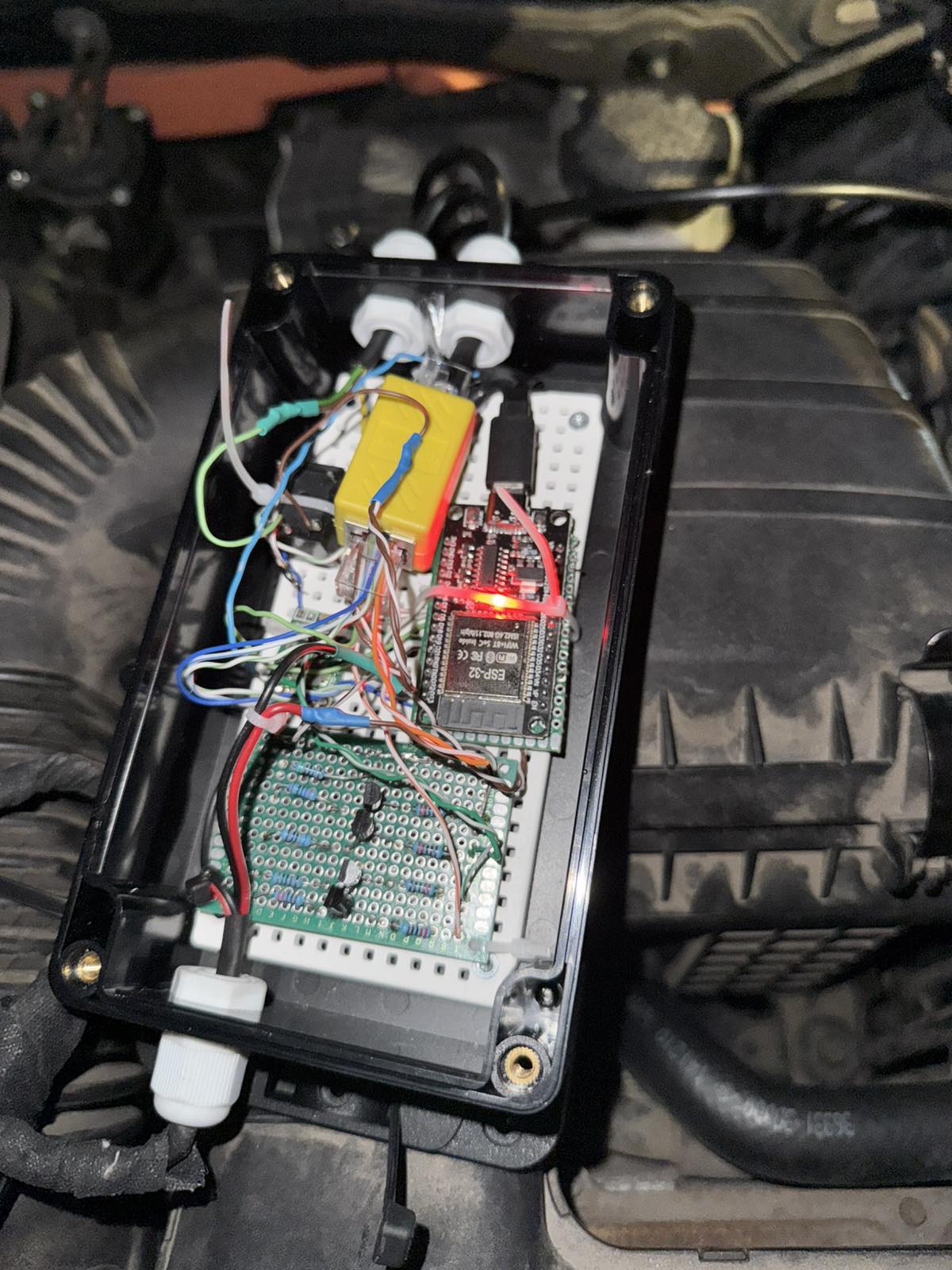
The first working version was built around an ESP32. It measured the signal from the old NTC sensor through an analog input, calculated the resistance and temperature, and then used transistors to switch the required resistor channels. In other words, the ESP32 did not replace the sensor with a digital signal directly. It controlled a physical resistor matrix, which the car’s control unit saw as a normal passive resistance.
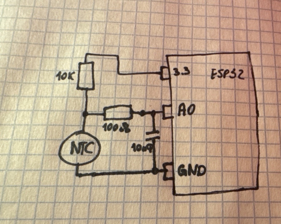
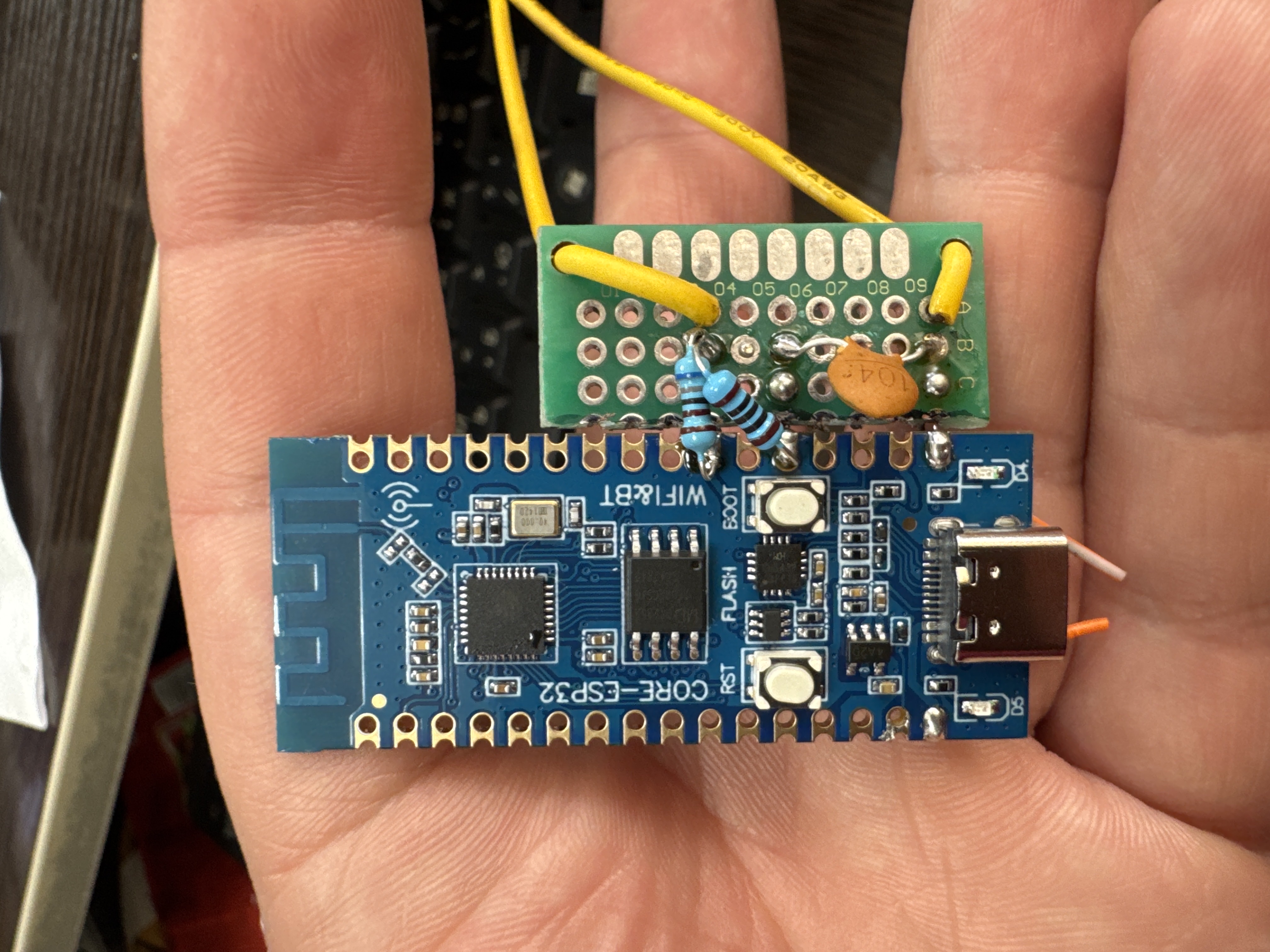
The circuit had a base resistor of 5.1 kΩ, which was always connected. This was important as a basic and relatively safe default state: even if the additional channels were not active, the output would still have a defined resistance value instead of a complete open circuit. In addition to the base resistor, there were five parallel resistor channels: 6.8 kΩ, 2.2 kΩ, 1.0 kΩ, 680 Ω, and 220 Ω.
Each channel was controlled by a separate ESP32 GPIO pin through a transistor switch. In the code, these channels correspond to bits in a mask: if a bit is enabled, the corresponding resistor branch is connected in parallel with the base resistor. With five channels, the circuit can generate many different equivalent resistance combinations.
The logic of the code works like this: the ESP32 reads the voltage on analog input GPIO34; to make the reading more stable, it averages 64 samples; from the voltage divider value, it calculates the resistance of the old NTC sensor; using the old sensor model, approximately 100 kΩ / B=4200, it calculates the real temperature; then it converts that value into the resistance that the newer sensor, approximately 10 kΩ / B=3450, should have at the same temperature; the program selects the closest resistor-bank combination; the ESP32 turns on the required transistor switches; and the car’s control unit no longer sees the old 100 kΩ sensor directly, but instead sees an equivalent resistance similar to the expected 10 kΩ sensor.
The code also builds a table of all possible resistor combinations. During startup, the program checks all 32 possible masks, calculates the equivalent resistance for each one, and also calculates what temperature that resistance would represent for the facelift control unit. Then these combinations are sorted from “cold” to “hot.”
To prevent the circuit from switching back and forth too often near a boundary between two values, the code includes hysteresis logic. This means that one temperature threshold is used to move to the next step, and a slightly lower threshold is used to move back. This reduces unnecessary switching when the temperature is hovering near a transition point.
There is also a parameter in the code called T_ADVANCE_C = 10°C. This means that the switching logic does not use only the calculated temperature from the old sensor. It uses the calculated temperature plus a small offset. In other words, the circuit intentionally advances the reaction a little so that the control unit sees the transition into the next temperature range earlier.
Besides the main resistance-conversion function, I also added indication and monitoring. The circuit had regular RGB LEDs as well as an addressable NeoPixel. The color indicated the approximate temperature state: cold, normal, elevated temperature, or dangerously high temperature. This was useful because I could visually see that the device was working and understand roughly what temperature range it was operating in.
The ESP32 also created its own Wi-Fi access point called HEVOptimaNTC. Through a web page, I could see the current parameters: input voltage, calculated resistance of the old sensor, calculated temperature, target resistance, active resistor combination, and the temperature that the control unit approximately “saw.” In addition, the code also included BLE monitoring: the device could send JSON data with the real temperature, output resistance, and active resistor combination.
The whole circuit was powered through the cigarette lighter line. When the cigarette lighter circuit became active, it triggered a relay, and that relay powered the converter. The relay was not used to switch the temperature signal itself. It was used only to organize the power supply for the aftermarket device in a more “proper” way. The converter was not permanently powered; it turned on together with the car when needed.
This first version worked for quite a long time. It was not perfect in terms of accuracy because the output resistance changed in steps rather than as a smooth curve. But it was already much better than a single parallel resistor. It did not simply fix the temperature in one artificial range. It tried to adapt the signal from the old sensor to the logic expected by the newer control unit.
In practice, this was the first real prototype of the NTC converter. It proved that the problem could be solved not by replacing the transmission again and not by opening the transmission, but by electronically matching two different sensor characteristics. The old sensor remained in place, the ESP32 read its behavior, and the control unit received a converted signal close to what it expected from the newer sensor.
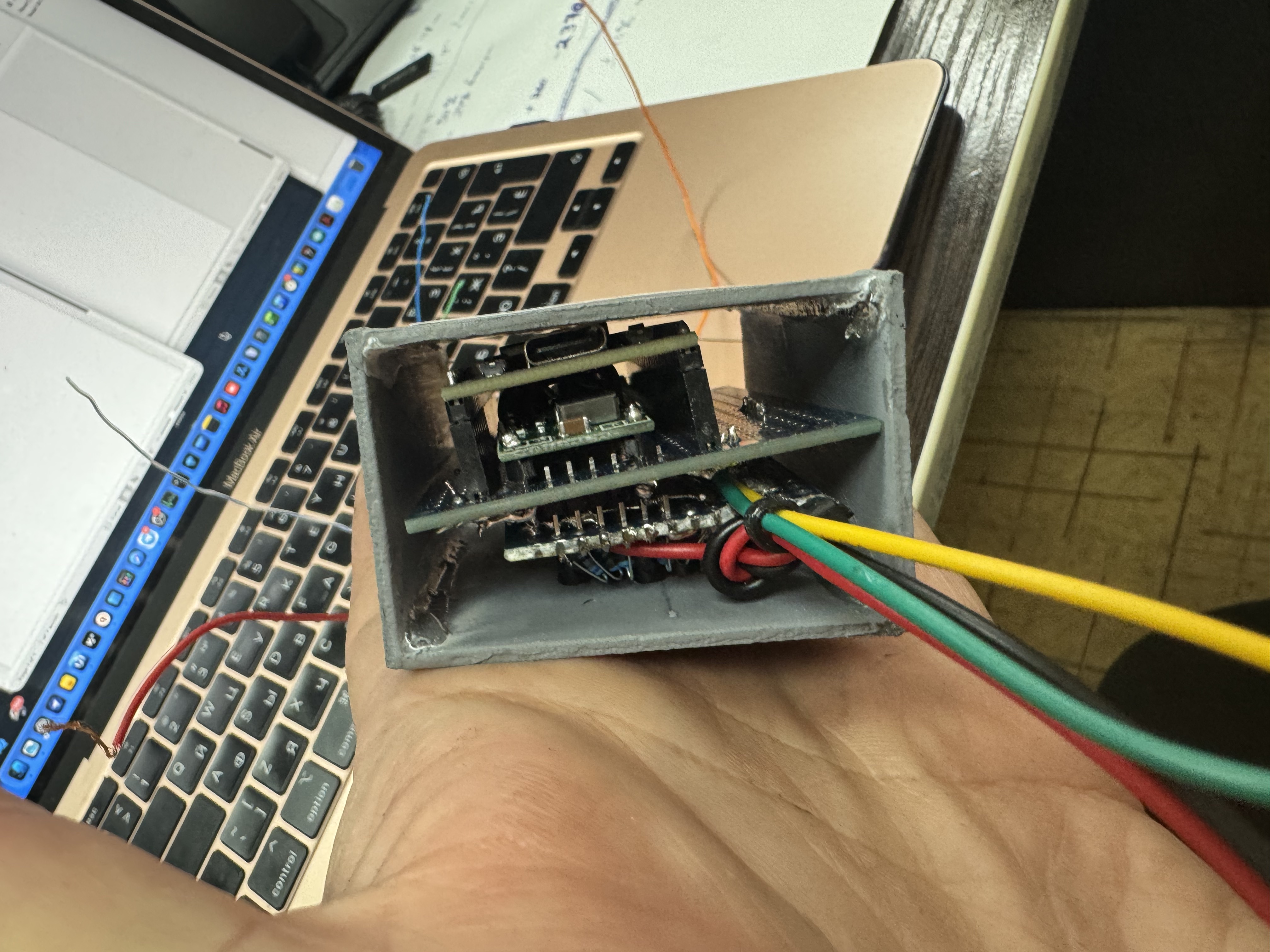
12. Improved Converter Version: power relay-free compact Solution
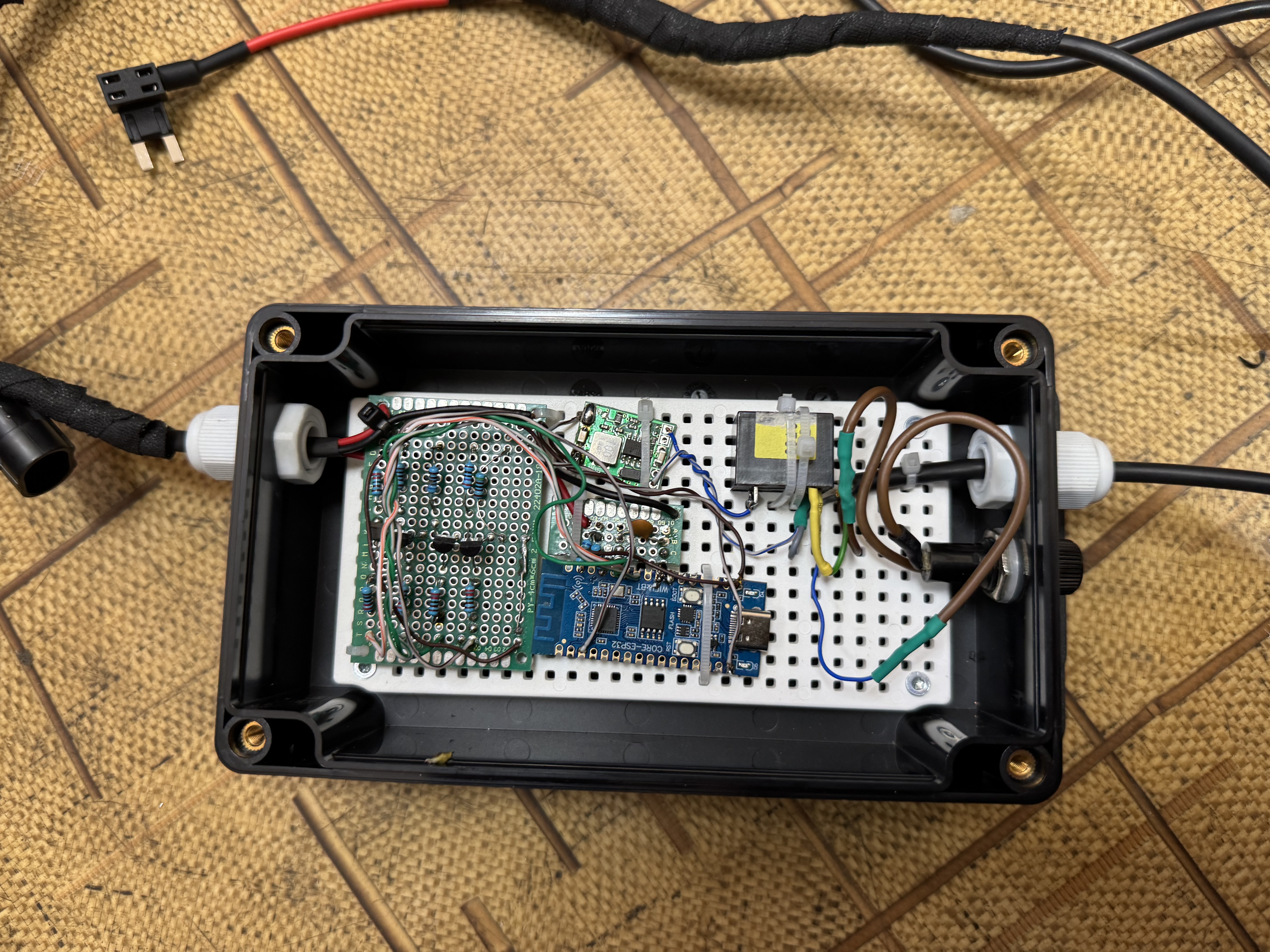
After the first working version had been installed and tested for some time, I decided to improve the design. The first prototype proved that the idea worked, but physically it was not very elegant. Under the hood, there was a relatively large box with wires, resistor branches, switching circuits, and the ESP32 controller. It worked, but it still looked like a prototype rather than a clean final solution.
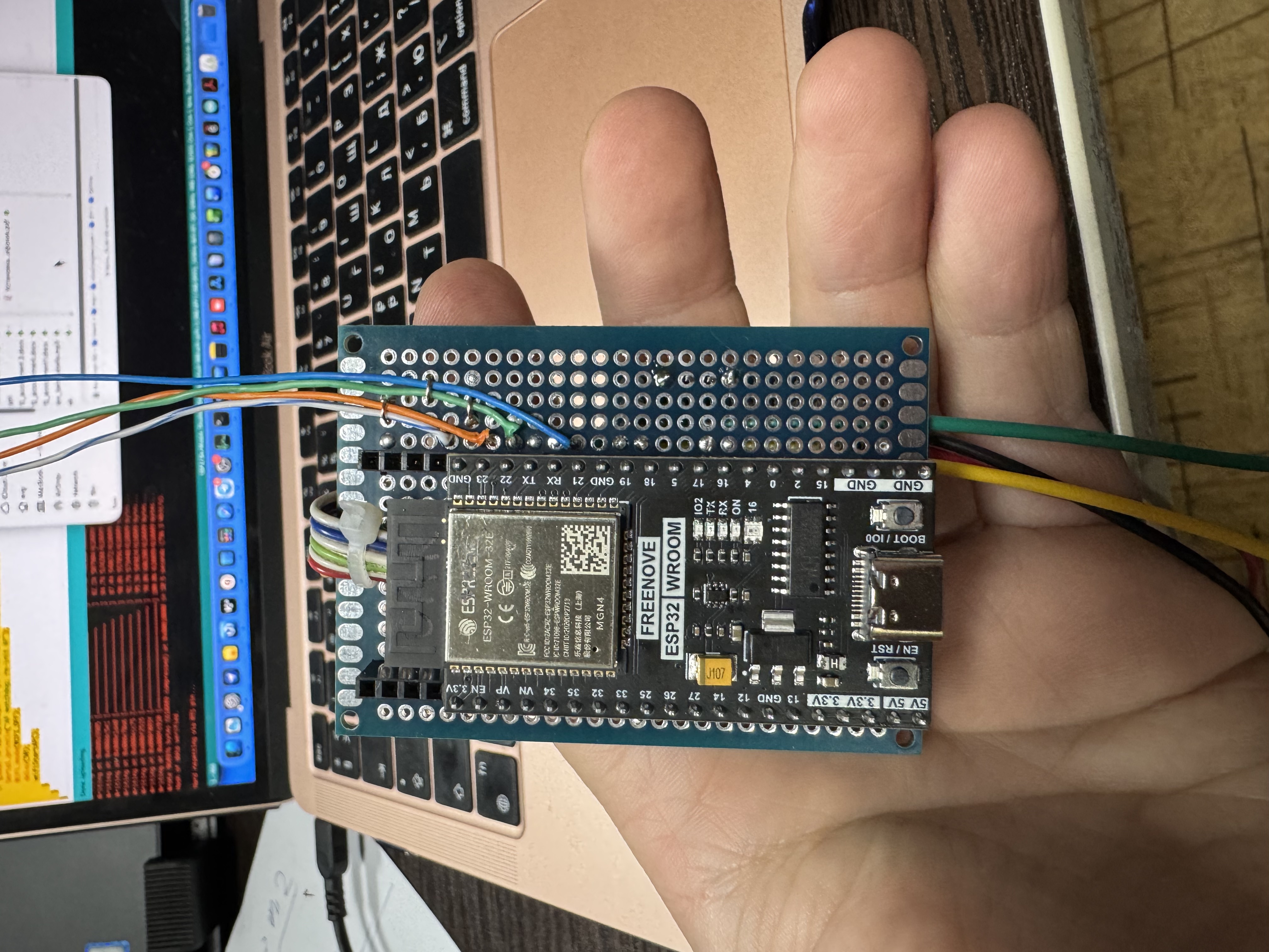
At the same time, I bought a better-quality ESP32 development board — a Freenove ESP32 board. That gave me a good reason to rebuild the converter more properly. I wanted the new version to be more compact, cleaner, more reliable, and easier to service if anything went wrong later.
The main idea stayed the same: the converter still reads the old 100 kΩ-type NTC sensor, calculates the approximate real temperature, and then provides the car’s control unit with an equivalent resistance that looks like the newer 10 kΩ-type sensor. But the physical implementation became much neater.
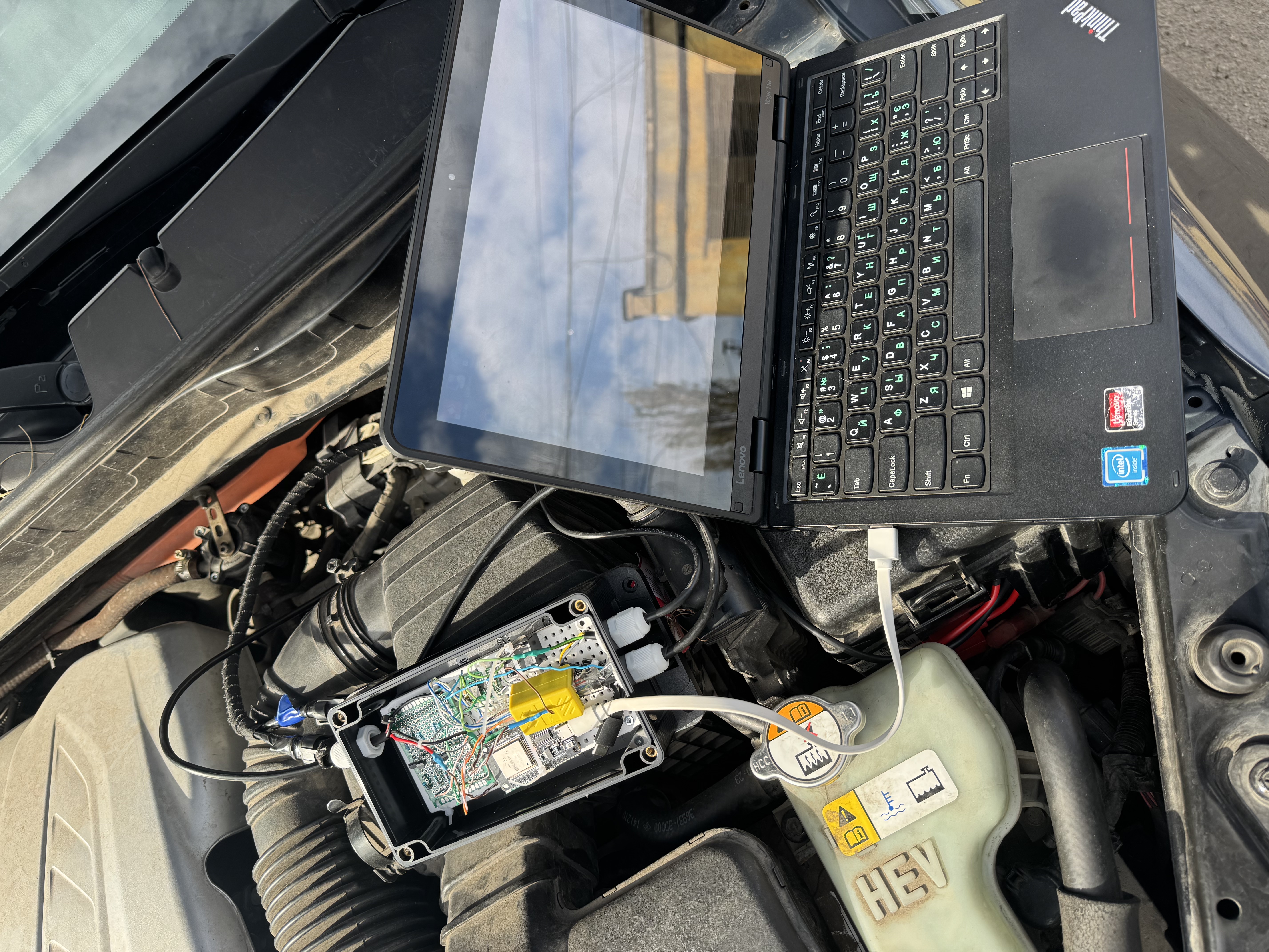
Instead of keeping a large box with wiring under the hood, I moved the electronics into the cabin, near the interior fuse box area. This made the installation more compact and protected the controller from the harshest conditions under the hood, such as heat, moisture, dirt, and vibration. The wiring became shorter and more organized, and the whole device looked much less like a temporary experiment.
I also simplified the power supply. In the earlier version, the converter was powered through a relay triggered by the cigarette lighter circuit. In the improved version, I powered the converter directly in parallel from one of the cigarette lighter power lines. For this type of low-power electronic device, that was enough. The converter turns on together with the car’s accessory power and does not need to be powered permanently.
One important part of the improved version was the dashboard indicator. I installed a small RGB LED on the panel so I could always see that the system was alive and understand roughly what temperature range it was reading. This was not just decorative. It became a simple diagnostic indicator for the converter.
According to the logic in the code, the LED works as a temperature status display: below 60°C, the indicator blinks blue; from 60°C to 90°C, it blinks blue and green together, visually showing a cyan/blue-green state; from 90°C to 105°C, it blinks green; from 105°C to 120°C, it blinks red; from 120°C to 130°C, it stays solid red; and above 130°C, it blinks red rapidly as an alert condition.
The same indication logic is also duplicated on the onboard NeoPixel LED of the ESP32 board. This means that both the external dashboard RGB LED and the small built-in addressable LED can show the operating state of the converter.
For me, this indicator is very useful. When the LED is blinking or showing the expected color, I know that the converter is powered, the ESP32 is running, and the temperature logic is active. If the LED ever goes completely off, I immediately know that something is wrong with the converter power, controller, or indication circuit.
At the same time, the design still has a basic fail-safe idea. The output resistor network includes a base resistance that remains as the default state. So even if the controller stops switching the additional resistor branches, the control unit should still see a defined resistance value rather than a complete open circuit. In practical terms, this means that if the converter has a problem, the system should not instantly return to the same P0A2D open-circuit-style fault. The car should still see a basic resistance value, and I would be able to continue driving carefully and repair the converter later.
This was important to me because I did not want the car to depend on a fragile experimental device in a way that could leave me stuck immediately. The goal was not only to make the signal correct, but also to make the system predictable. If everything works, the converter actively adapts the signal. If something fails, the base resistance still gives the ECU a reasonable fallback signal, and I can fix the device when I get home or reach a safe place.
The improved version still uses the ESP32 to perform the main logic: read the sensor, calculate the old NTC temperature, select the required equivalent resistance, and control the resistor branches. It also still provides monitoring through Wi-Fi and BLE, so the live data can be checked if needed. But physically, it became a much cleaner and more practical installation.
In the end, this became the version I continued driving with. It was compact, installed inside the cabin near the fuse box, powered from the cigarette lighter circuit, and monitored with a small RGB indicator on the dashboard. Compared with the first under-hood prototype, it felt much more like a real working solution and much less like a temporary experimental setup.
This version did not require removing the transmission again, replacing the internal sensor, or arguing further about the used gearbox. Instead, it solved the compatibility problem electronically: the older sensor remained inside the replacement transmission, while the converter translated its signal into something the newer control unit could understand.
13. Final Verification with Mucar Live Data
After building the improved converter, I still needed to verify that the car’s control unit was really interpreting the converted signal correctly. It was not enough for the ESP32 to calculate values internally. The important question was what the vehicle itself saw through its diagnostic system.
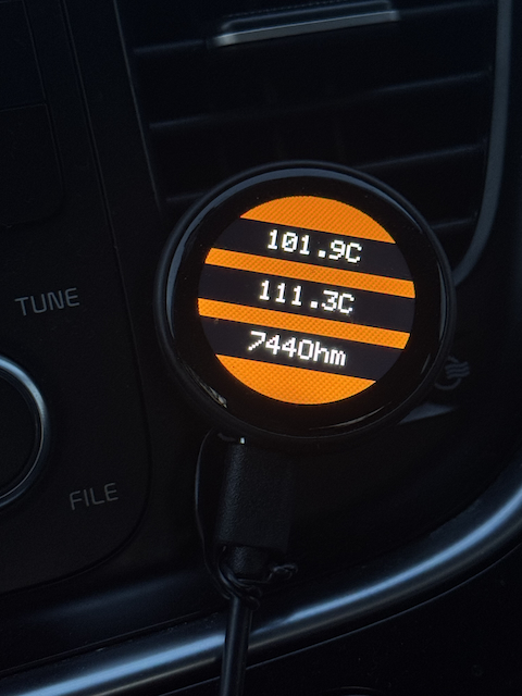
For monitoring, I built a small temperature display using a round IPS LCD screen. This display showed the key values from the converter in real time: the calculated real temperature from the old 100 kΩ-type sensor, the temperature equivalent that was being sent to the control unit, the current output resistance generated by the converter, and the active resistor combination or operating step.
This made the system much easier to understand while driving. Instead of guessing what the converter was doing, I could see the current state directly. I could compare the real calculated temperature with the temperature that the car should be seeing, and I could also see how the output resistance changed as the converter switched between steps.
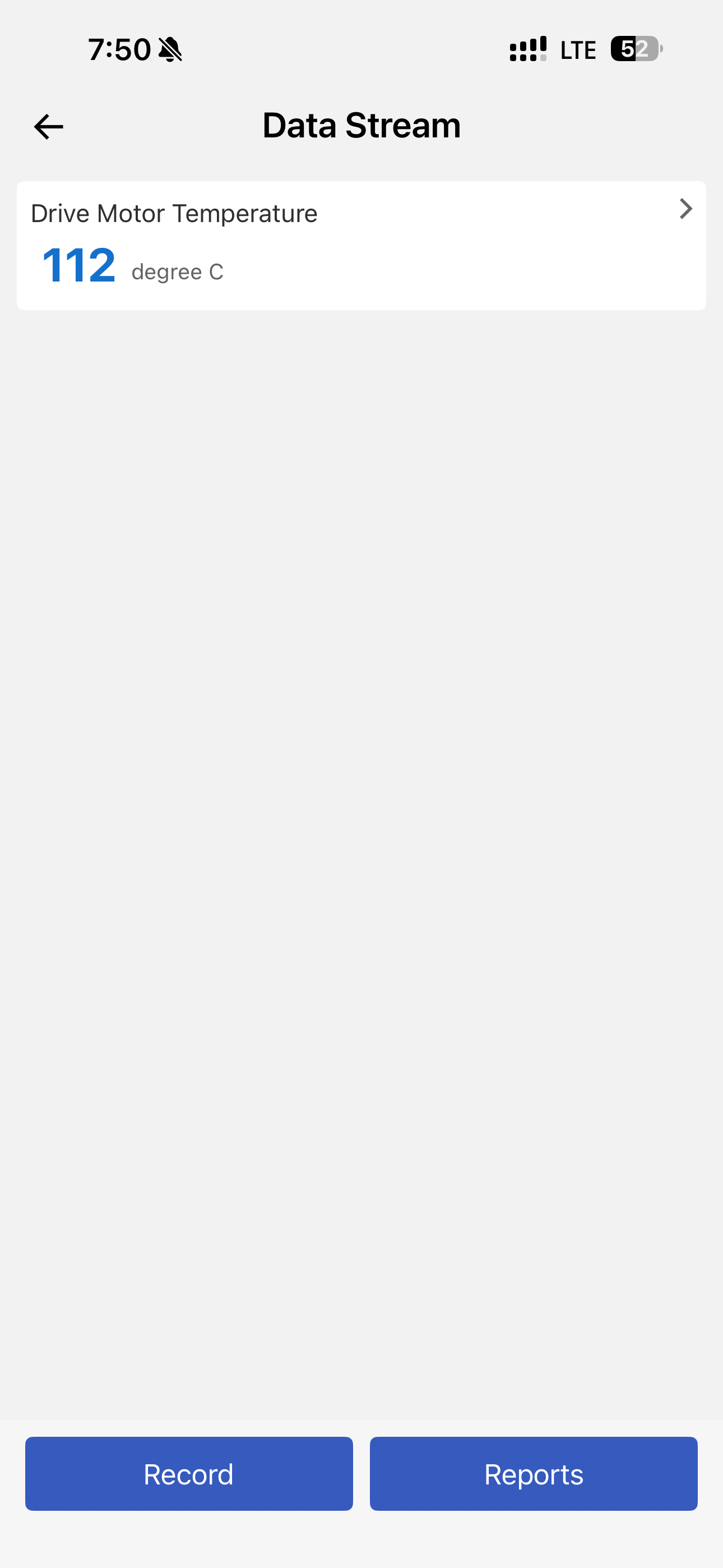
Later, I bought a Mucar BT200 diagnostic scanner. This was important because the final confirmation had to come not from my own display, but from the car’s live data. The converter could show one thing internally, but the real goal was for the vehicle’s control unit to interpret the signal correctly.
Using Mucar live data, I checked how the control unit interpreted the converted temperature signal. I went through the different temperature steps and compared what my converter was outputting with what the car was showing through diagnostics. The result was successful: the ECU interpreted the temperature steps correctly, with only minimal deviation.
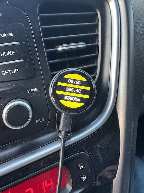
This was the key validation point. It confirmed that the converter was not just electrically preventing the P0A2D fault, but was actually producing a signal that the car understood as a realistic electric motor temperature. The control unit was no longer seeing an open circuit, excessive resistance, or an invalid sensor value. Instead, it saw a normal temperature signal within the expected range.
The verification also showed that the stepped output was acceptable in practice. Of course, it was not a perfectly smooth analog NTC curve, because the converter used a resistor bank. But the steps were close enough for the control unit to interpret them correctly, and the difference between the converter output and the scanner reading was small enough to be practically usable.
After that, I continued driving the car with this system installed. At the time of writing, I have been driving with this converter for about eight months. During this period, there have been no transmission-related fault codes caused by the temperature sensor issue. The gearbox has been working normally from the diagnostic point of view, and the previous P0A2D problem has not returned.
For me, this was the real proof that the solution worked. The car was no longer stuck in a repeated cycle of clearing the fault, driving a few kilometers, getting a kick, and then continuing in fault mode. Instead, the hybrid system could operate normally, and the control unit received a temperature signal it could understand.
In the end, the final verification was not only the scanner reading, but also real everyday use. A temporary fix can work for one test drive, but a proper solution has to survive normal driving, temperature changes, vibration, restarts, and daily use. After months of operation without gearbox-related errors, the converter proved itself as a practical working solution.
Back to top ↑14. Risks, Limitations, and Reliability Considerations
Of course, this solution also has risks and limitations. It is important to describe them honestly, because this is not a factory repair and not a standard OEM procedure. It is a custom electronic modification created to solve a very specific compatibility problem between two versions of the hybrid transmission temperature sensor.
The first obvious risk is resale perception. For a future buyer, any non-factory modification inside a hybrid vehicle can raise questions. Even if the solution works correctly, the presence of an additional electronic converter may create doubt. This is understandable: most buyers prefer a car where all systems are original and untouched. A custom ESP32-based converter, even if technically logical, still looks like a modification, and not everyone will be comfortable with that.
The second limitation is related to the minimum temperature that the converter can represent. The resistor network is built around a base resistor, and all other resistor branches are added in parallel to it. Because of this design, the highest output resistance is limited by the base resistor. In my configuration, this means that the lowest temperature the control unit can see is around 44°C. So even in cold weather, the ECU does not see a fully cold electric motor temperature. It immediately sees approximately 44°C as the minimum value.
This is not ideal from a theoretical point of view, but in practice I do not consider it critical. The most important operating area for this signal is not deep cold start accuracy. The most important area is warm and hot operation, where the control unit must correctly understand when the motor is heating up and when protective logic may be needed.
The converter was tuned mainly to provide useful accuracy in the warm and hot temperature range. That is the range where overheating protection actually matters. If the car slightly overestimates temperature at startup, this is much less dangerous than underestimating the temperature when the motor is already hot. From a safety point of view, it is better for the ECU to think the motor is a little warmer than it really is than to miss a real overheating situation.
For the same reason, I intentionally added a 10°C advance in the converter logic. Internally, the system does not switch the output only according to the calculated real temperature. It uses the calculated temperature with an added offset. The idea is simple: the control unit should see the motor as slightly hotter in advance, so it can react earlier and take measures to prevent overheating.
In other words, the converter is not tuned to make the displayed temperature look perfect in every possible condition. It is tuned to keep the signal valid, believable, and conservative in the temperature range that matters most. The priority is to avoid a sensor fault and to make sure the control unit receives a temperature signal that helps prevent overheating rather than hide it.
The third limitation is the reliability level of the electronics. An ESP32 development board is not an automotive-grade Siemens, Bosch, or OEM control module. It was not designed from the factory to live for many years in a vehicle environment with vibration, voltage spikes, temperature changes, and electrical noise. This has to be understood clearly.
To reduce this risk, I used a higher-quality ESP32 board with good reviews, better soldering quality, and better components. I also moved the electronics into the cabin near the interior fuse box area instead of leaving a large box under the hood. This reduced exposure to heat, moisture, dirt, and vibration. The installation became cleaner and more protected.
The probability of failure still exists, but in my opinion it is low enough for practical use. The device has a relatively simple job: measure an analog signal, calculate a value, and switch resistor branches. It is not controlling brakes, steering, throttle, or high-voltage switching directly. It only adapts the temperature sensor signal so that the control unit can interpret it correctly.
I also added two additional layers of confidence. The first one is the base resistance. Even if the ESP32 stops switching the additional resistor branches, the ECU should still see a defined resistance instead of a complete open circuit. This reduces the chance of the car immediately detecting the same temperature sensor circuit fault.
The second one is visual indication. I have a small RGB LED indicator on the dashboard. It shows that the converter is powered and gives me a quick visual confirmation that the system is alive. If the indicator goes off completely, I know that something is wrong with the converter power, controller, or indication circuit. In that case, the car should still remain on the base resistance, and I can continue carefully until I reach a safe place and fix the issue.
Another limitation is that the converter does not create a perfectly smooth analog NTC curve. It uses a resistor bank, so the output changes in steps. However, during verification with Mucar live data, the control unit interpreted these steps correctly, with only minimal deviation in the useful operating range. From a diagnostic and practical driving point of view, the result proved to be acceptable.
So the solution is not perfect and not factory-original. It is a controlled engineering workaround. It solves the compatibility problem, avoids removing the transmission again, and allows the car to operate normally with the replacement gearbox. But it also requires understanding, monitoring, and responsibility from the owner.
For me, the balance was acceptable. The alternative was to remove the transmission again, search for another rare hybrid gearbox, argue with the supplier, or open the transmission to replace the internal sensor. Compared with that, a compact, monitored, fail-safe-oriented converter was the most reasonable solution in my situation.
Back to top ↑15. Lessons Learned
This story gave me several important lessons. Some of them are specific to the Kia Optima Hybrid, but most of them are much broader and can apply to any complex used car, especially one with hybrid technology.
The first lesson is that you have to diagnose much more carefully what you are buying. At the time of purchase, the car looked attractive: a large sedan, good comfort, a hybrid system, fuel efficiency, pleasant driving behavior, and the feeling of a higher-class vehicle. But even if a car looks good and drives normally, it does not mean that there are no hidden problems inside that may appear a week later or several months later.
The second lesson is that before buying a car, you should carefully read about the typical problems of that exact model, that exact version, and that exact hybrid system. It is not enough to watch general reviews or hear that “the car is good.” It is better to search for real cases: which fault codes appear, what usually fails, how much repairs cost, whether parts are available, and whether there are mechanics nearby who actually know how to repair this system.
This is especially important when the budget is limited, but you want a large, good-looking, comfortable, and technologically advanced car. In that situation, you have to be honest with yourself: if a car is relatively affordable for its class, age, and equipment level, part of the risk is already included in the price. In other words, when you do not have unlimited money but you want a big “cool” sedan, you should be prepared that some complex problem may eventually appear.
The third lesson is that complexity always has a price. A hybrid system gives many advantages: fuel economy, quiet operation, interesting power management logic, regenerative braking, and the feeling of a modern car. But you pay for that with more difficult diagnostics, more expensive components, fewer specialists, and more possible failure points.
In a simple car, many problems can be solved quickly and relatively cheaply. In a complex car, one fault can lead to another: clutch pump, cooling, electric motor, inverter, temperature sensor, control unit, calibration. The more complex the system is, the higher the chance that the problem will not be obvious and will require not just replacing a part, but understanding how the whole system works.
The fourth lesson is that mechanical compatibility is not enough. In my case, the replacement transmission physically fit the car, but the temperature sensor inside it had a different electrical characteristic. This showed me that in a modern vehicle, “fits by part classification” does not always mean “will work without problems.” Electronics, sensors, and calibrations can be just as important as the mechanical assembly itself.
The fifth lesson is that sometimes an engineering approach can save the situation. If I had looked at the problem only as a standard repair, there were not many options: remove the transmission again, search for another one, argue with the supplier, or open the transmission. But once it became clear that the problem was caused by different NTC sensor curves, the task changed from “repairing the gearbox” into matching an electrical signal.
The sixth lesson is that a temporary solution can be useful if it is done consciously. The parallel resistor was not a proper final repair, but it helped confirm the direction. It showed that the control unit was reacting specifically to resistance, and that the problem could be solved by correcting the signal. After that, it became possible to build a more advanced and more correct converter.
The seventh lesson is that in complex systems, verification with real data is essential. It is not enough to build a circuit and say that it works. You need to check what the vehicle itself sees through diagnostics. In my case, Mucar live data became an important confirmation that the control unit was really interpreting the temperature steps correctly.
The main conclusion for me is this: a complex car can give a lot of satisfaction, but it also requires a higher level of responsibility. If you buy a hybrid, a large sedan, or any technologically advanced car on a limited budget, you should be ready not only for comfort and pleasant driving, but also for complicated diagnostics, non-obvious problems, and solutions that sometimes you have to find yourself.
Back to top ↑16. Conclusion
Looking back at this whole story, I can say that it became much more than just a car repair. It started as a failure of a hybrid transmission, but eventually turned into a real engineering case involving diagnostics, electronics, resistance measurements, NTC curves, microcontroller programming, signal conversion, and practical testing in a real vehicle.
As an engineer, I received very valuable experience from this situation. I had to understand how the hybrid system works, how the control unit interprets a temperature sensor, how different NTC characteristics affect diagnostics, and how to build a converter that can translate one sensor curve into another. This was not just theory. It was a practical task where the result directly affected whether the car could drive normally or not.
This experience was also useful for my education and technical development. It connected several areas at once: automotive diagnostics, electronics, embedded systems, programming, measurement, troubleshooting, and systems thinking. In a way, the car became a real laboratory. The problem was unpleasant and expensive, but it forced me to study the system much more deeply than I ever would have done if everything had simply worked.
At the same time, I clearly understand that this situation could have been a very serious problem for a regular car owner who is far from electronics, diagnostics, and engineering. If I had not been able to search technical information, measure resistance, understand the difference between 10 kΩ and 100 kΩ NTC sensors, write code for an ESP32, and verify the result with diagnostic live data, I would probably have had only very expensive options.
A regular owner in this situation might have been forced to remove the transmission again, argue with the supplier, search for another rare gearbox, pay for repeated labor, or open the transmission to replace the internal sensor. Without technical knowledge, it would be very difficult to understand that the transmission itself could be working, while the actual problem was only the electrical characteristic of the temperature sensor.
That is why this case showed me both sides of owning a complex hybrid car. On one side, it is a modern, comfortable, efficient, and technically interesting vehicle. On the other side, when something goes wrong, the problem may not be simple or obvious. A small sensor mismatch can turn into a serious diagnostic challenge, especially when the system combines mechanical, hydraulic, electrical, and software logic.
In my case, the final solution was a custom NTC signal converter. It allowed the car’s control unit to correctly interpret the temperature signal from a transmission with an older-type sensor. The solution is not factory-original, and it has its limitations, but it has been working in real use for months without transmission-related fault codes. Most importantly, it solved the problem without removing the transmission again.
The main lesson from this story is that a complex system requires a complex way of thinking. Sometimes the correct repair is not just replacing a part. Sometimes it is understanding what the system expects, what it actually receives, and how to make those two things match. For me, this was a stressful and expensive experience, but also a strong engineering lesson that connected theory with real life.
Back to top ↑